
Frontier AI labs and infrastructure providers are looking to add every last megawatt of power to their portfolio. Yet, several megawatts of AI capacity are hiding in the power delivery system. Electricity is lost as it passes through converters, distribution equipment and rack power supplies. At the scale of an AI campus, recovering even a few percentage points changes how much compute a site can support and the total cost of operations (TCO) across years.
The transition to 800-volt direct current (800 VDC) targets those losses by moving higher-voltage power closer to the compute and removing unnecessary conversion stages. For the AI industry waiting on additional supply, that creates another avenue to growth: make more of the secured power available to compute.
Higher Voltage Makes Denser Racks Practical
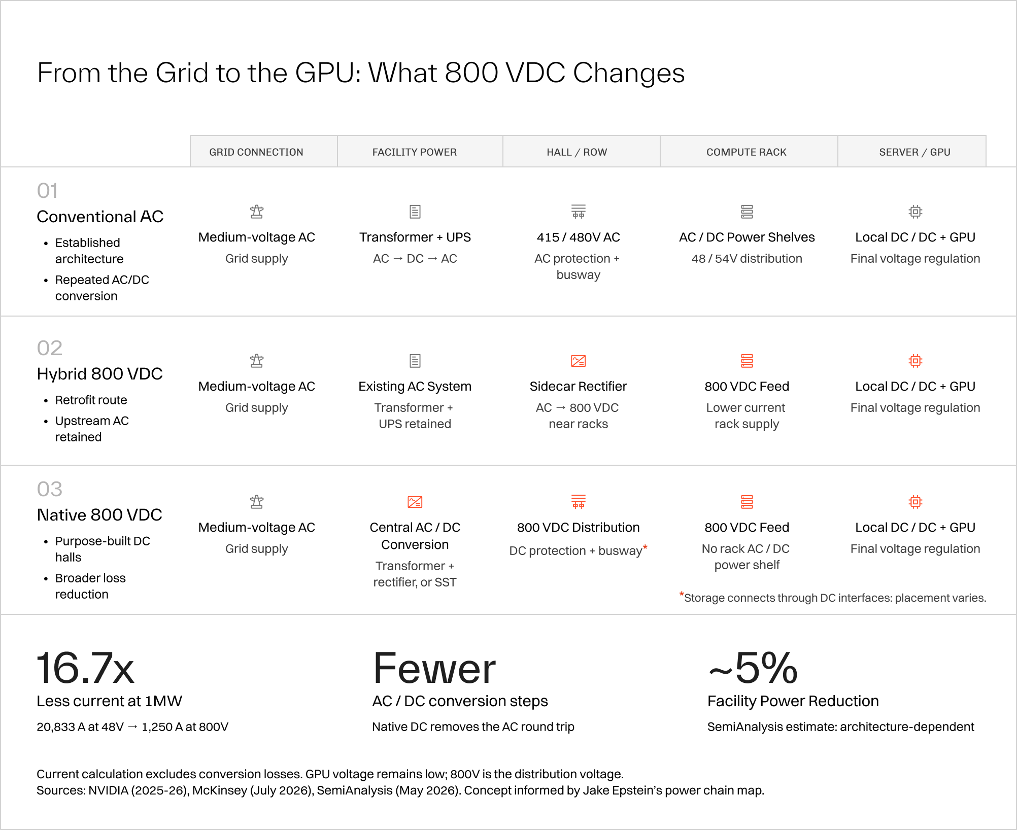
The central change is where voltage is reduced. In a conventional data center, medium-voltage alternating current (AC) is stepped down and distributed toward the racks, typically at 415V or 480V AC. Rack power supplies convert it to DC, commonly at 48–54V, before further conversion supplies the much lower voltages required by the chips.
That arrangement becomes demanding as rack power increases. As GPUs get more powerful and evolve into rack scale systems, their Thermal Design Power (TDP) has also increased continuously. For context, the NVIDIA H200 has a TDP of 700W whereas a Rubin GPU can go up to 2300W (190 kW to 230 kW per rack).
Delivering 1 MW at 48V requires approximately 20,833 amps. At 800V, the same power requires 1,250 amps. These figures compare DC distribution voltages and exclude conversion losses; the upstream facility already distributes power at higher AC voltages.
800VDC carries higher-voltage DC closer to the hardware, then steps it down near the load. The GPUs still operate at low voltage, but very high current travels a shorter distance. That reduces the burden on conductors, connections and rack space.
The change can begin beside a single rack or extend across an entire hall. That flexibility is important: data center operators can introduce higher-voltage DC around new hardware while retaining useful parts of an existing data center.
How 800 VDC Eases Power Constraints
The lower current changes both the physical design and the amount of electricity consumed in delivery. These are some of the effects that matter the most:
- Deliver the same power at much lower current. A 600 kW load requires 12,500 amps at 48VDC, versus 750 amps at 800VDC. At 1 MW, the comparison is 20,833 amps versus 1,250 amps.
- Less copper and less resistive heating. Conductor losses rise with current squared. Reducing current shrinks cables and busbars and reduces losses.
- Fewer conversion losses. A conventional double-conversion UPS turns AC into DC and back into AC; rack supplies then convert it to DC again. A native DC architecture can remove that return to AC and subsequent rectification. Local DC-to-DC conversion remains, but avoidable intermediate steps disappear.
- Make room for compute. SemiAnalysis estimates 5% lower facility consumption from the transition. That creates potential room for growth within the existing supply limit.
- Buffer workload swings when combined with storage. Capacitors and batteries supply or absorb power during rapid GPU load changes, reducing the fluctuations transmitted upstream.
These gains have different consequences at different sites. Some AI factories need to fit a new rack generation into an existing hall. Others might have room to expand but cannot obtain additional utility capacity. The transition to 800 VDC can help each, although the deployment and the resulting savings will differ.
Consider a campus averaging 1 GW of facility demand. A 3–5% reduction in electricity consumption at unchanged compute output would save 30–50 MW continuously. At 5%, that amounts to 438 GWh a year.
For a growing campus, much of that recovered power could support additional compute. A 5% reduction in energy per unit of output would allow 5.26% more output within the same power budget*, provided the hardware, cooling and networking can support it.
*Peak demand and redundancy conditions must be validated before treating average savings as dependable capacity.
Inside the 800 VDC Power System
The power delivery system has four jobs: convert the incoming supply, distribute it to the racks, buffer sudden changes in demand and isolate faults.
Convert AC to 800 VDC. A rectifier converts the incoming AC into the 800 VDC supply that feeds the compute hardware.
Carry power to the racks, then lower the voltage. DC-rated cables or busways carry the 800V supply to the compute hardware. Local DC/DC converters and voltage regulators reduce it to the voltages the chips require.
Use storage to buffer sudden changes in demand. When GPU demand rises sharply, capacitors and batteries can supply part of the increase instead of passing the entire spike to upstream equipment. They recharge when demand falls. This smooths the power drawn from the supply, but does not reduce the workload’s energy requirement.
Disconnect faults without taking healthy racks offline. A short circuit can draw a rapid discharge from nearby capacitors. Protective devices must interrupt the affected circuit, while converter controls limit the current supplied into the fault. Coordinating those responses keeps a local fault from shutting down a larger group of racks.
What are the paths to deployment
The transition starts with a choice about how far upstream to move conversion. Existing facilities have infrastructure worth preserving; new halls have more freedom to redesign the power path. That produces three main deployment routes.
A sidecar confines the change closer to the new hardware. It is a practical way to introduce 800 VDC into an AC facility, but it retains upstream losses and still depends on the existing system having enough capacity. Its immediate value is often making the rack deployable.
A native DC hall moves conversion farther upstream. This offers the greatest freedom to simplify the chain and organize the building around high-density compute. It can use conventional transformers paired with rectifiers; it does not have to wait for solid-state transformers (SSTs), which integrate conversion through power electronics and high-frequency magnetics.
Choosing the Right Architecture for the Site
For an existing facility, first assess whether the electrical capacity, available space, cooling and protection can support the planned racks. Weigh the work and disruption of a retrofit against the remaining service life of the installed equipment.
In a new hall, plan the electrical architecture alongside the compute requirements. Waiting until the GPUs have been selected can leave fewer options for simplifying the power chain and a building poorly suited to the hardware it must support.
Compare efficiency across the complete power path, accounting for the equipment removed and added, expected operating loads and redundancy arrangements. A converter’s peak efficiency says little about its performance in a facility that spends much of its life below full load.
Preserve infrastructure that still serves the deployment. Redesign the parts that limit it.
Fewer Components, Lower Lifetime Costs
A simpler power chain can also reduce construction and operating costs, particularly in new halls where the design can eliminate equipment from the outset.
- Lower capital expenditure. Removing conversion stages reduces the associated power modules, connections and installation work. Higher-voltage distribution also allows smaller conductors for a given power requirement, reducing copper and cable bulk.
- Less maintenance. Fewer conversion stages mean fewer components to inspect, service and replace. Moving power conversion out of compute racks can also make service access easier.
- Lower total cost of ownership (TCO). Electricity savings accumulate over the facility’s operating life, adding to potential reductions in equipment, installation and maintenance costs.
The Deployment Timeline: What Arrives When
Adoption is progressing at different scales. Early pilots are testing integrated designs while other sites introduce DC closer to individual racks.
Envision Energy’s 5 MW pilot at its Galaxy data center in Ulanqab, China, already uses solid-state transformers to convert 10 kV AC directly to 800 VDC for computing workloads. The company reports 98.5% conversion efficiency, compared with a typical 94–95%, giving the industry an early operating example as it builds the reliability record needed for wider adoption.
2026–2027 is the initial window for power racks and hybrid deployments. These approaches introduce 800 VDC near compatible compute while retaining existing AC infrastructure.
2027–2028 brings planned expansion at row and pod level. As deployments grow, shared power centers provide a way to organize conversion and storage around larger groups of racks.
2028–2030 is the expected window for broader facility-level DC adoption. More integrated designs, including those using solid-state transformers, depend on certification, operating experience and a mature supply chain.
AC, hybrid and native DC facilities will operate alongside one another. The important deadline for AI factories is the arrival of hardware its current electrical system cannot serve. Planning backward from that date turns an industry roadmap into concrete decisions about space, connection points, protection and procurement.
New generation and grid investment remain essential. But AI growth cannot depend entirely on securing another increment of supply. AI Factories also need to reduce what they lose in delivery and remove the physical barriers to powering denser compute.